Nec Chapter 9 Table 8
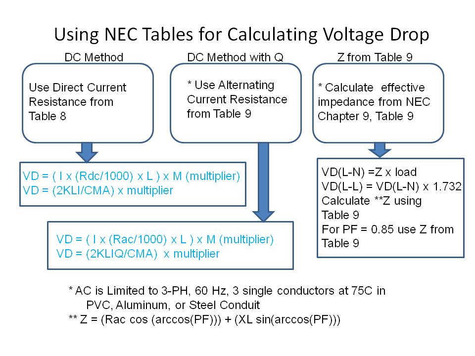
All you have to do is select conductor size ampere load single or three phase voltage number of parallel set of conductors coated or un coated conductors conductor length etc.
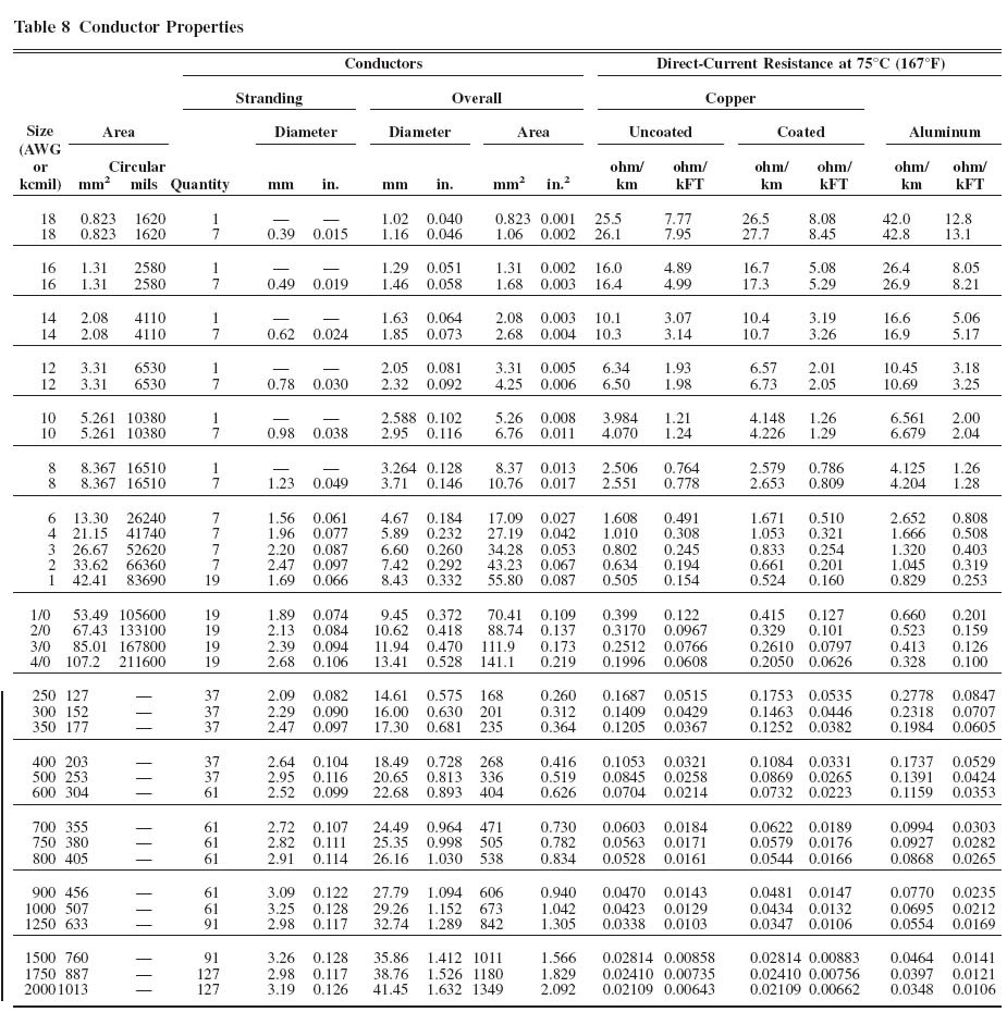
Nec chapter 9 table 8. The first four chapters of the nec apply to all installations except as modified by chapters 5 6 7 and 8. Dc resistance at 75c 167f awg or kcmil. Chapter 9 table 8. 3 2 nec chapter 9 tables 8 and 9.
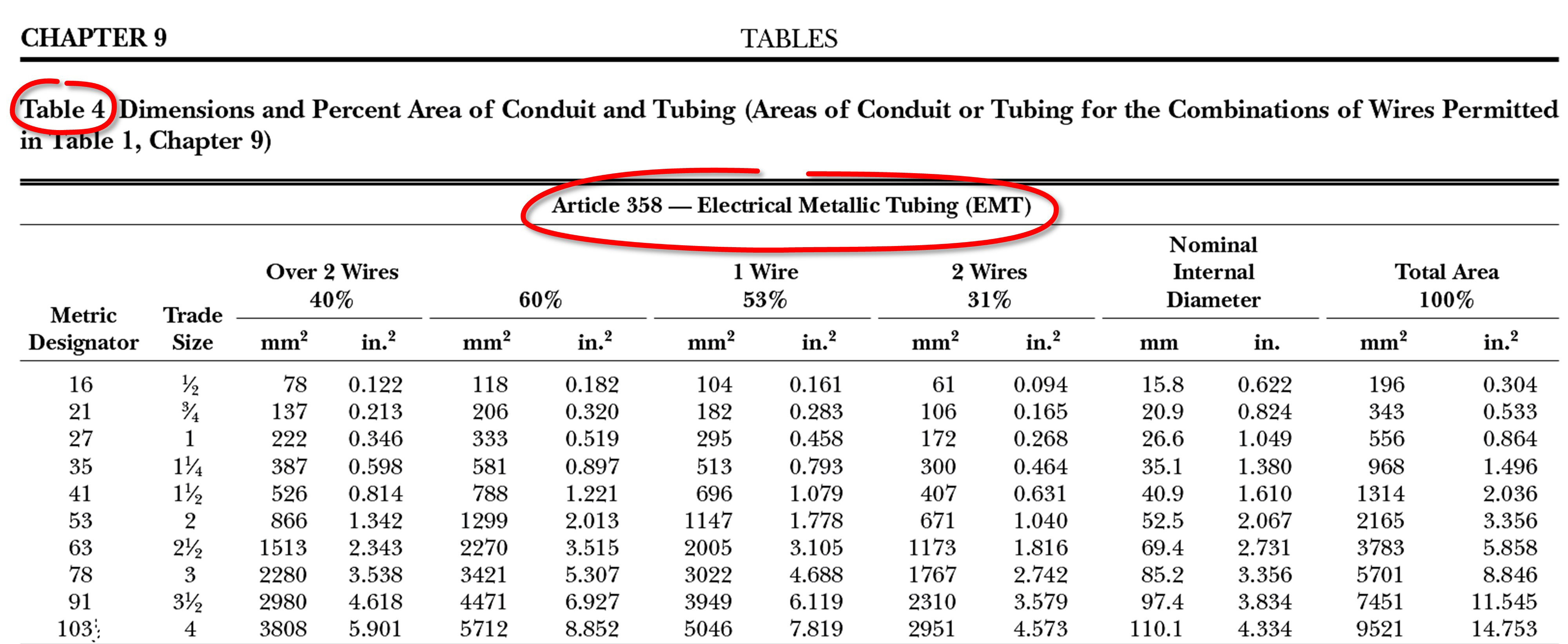
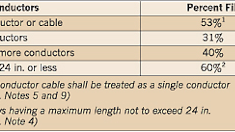
Dimensions and percent area of conduit and tubing see chapter 9 table 1 for allowed use of conduit area. Diam in area in diam in area in diam in area in 18. So why is it there and what use is it to you. Direct current circuit conduc tor resistances are listed in chapter 9 table 8 and alternat ing current circuit conductor.
U s method and today i will continue explaining how to use chapter 9 tables method for voltage drop calculations as follows. Chapter 9 table 4. R for al table r x 1 0 00333 x temp c 75 8 2 conductor resistance direct current circuits chapter 9 table 8 the nec lists the resistance and area in circular mils for both dc and ac circuit conductors. Chapter 9 doesn t modify anything.
Table 8 conductor properties. Some of you may find it odd that one of the two main headers in this table is shown as direct current resistance at 75 c. Nec table 8 conductor properties free download as pdf file pdf text file txt or read online for free. Awg kcmil thw thhw xhh xhhw thhn thwn.
Table 8 in chapter 9 provides a lot of data you can use in determining the resistance of copper and aluminum conductors and calculating voltage drop on your circuits. R 2 r 1 1 0 00323 t 2 75 for copper conductors r 2 r 1 1 0 00330 t 2 75 for aluminum conductors chapter 9 table 8 calculations are based on conductors at 75ºc if you would like to see how the values change when the temperature changes enter a new temperature value in the input box below. Nec chapter 9 table 5.
